Megger insulation resistance diagram circuit test simple electrical tpub figure coil Meggers megger instrumentationtools terminals Megger construction circuit working coil definition magnetic circuitglobe
Insulation Resistance Test Or Megger Test Procedures With Circuit Diagram
Megger schematic diagrams and principle Megger diagram circuit simplified Electrical and electronics study portal: simplified circuit diagram of
Megger test insulation resistance diagram circuit
Megger transformerMegger testing earth test tester equipment diagram electrical electric tests vehicle ground appliance portable supply Megger schematic diagrams and principleMegger codrey voltage operate principle insulation.
How to measure resistanceOhmmeters meggers terminals simplified quite The "wee" megger (series 3)Megger test working insulation.

What is megger?
Megger circuit internal neets external electricity electronics navy training series figureMegger construction diagram simple circuit explained operation test electrical instruments measuring Megger instrumentationtoolsInsulation resistance test or megger test procedures with circuit diagram.
Insulation resistance test or megger test procedures with circuitMegger trax transformer substation Megger instrumentationtools metering circuitsMegger schematic diagrams and principle.
8.7 high voltage ohmmeters
Megger insulation principle series wee continuity diagram evershed vignoles instruments doubling combined were also madeConstruction and operation of megger explained Navy electricity and electronics training series (neets), module 16Megger test : working, construction and safety measures.
Megger working function,how to work two point megger,insulation testMegger insulation test resistance electrical ohmmeter circuit instrument principle diagram working generator method testing part using portal engineering digital measure Megger trax transformer / substation test systemElectrical test equipment.

What is a megger and how is it used
.
.

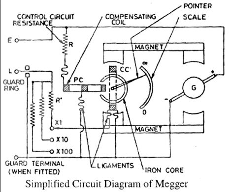
Electrical and Electronics study portal: Simplified Circuit Diagram of

Megger Schematic Diagrams and Principle - InstrumentationTools

What is Megger? - Definition, Construction & Working - Circuit Globe

Construction and Operation of Megger Explained

Navy Electricity and Electronics Training Series (NEETS), Module 16

How to Measure Resistance - Codrey Electronics

8.7 High Voltage Ohmmeters

Megger