Timer circuit countdown diagram electronic schematic down circuits count counter minute diy display pcb circuitos using gif schematics pt 10mhz Circuits timer circuit industrial delay simple electronic diagram make projects homemade solenoid single build application visit small electronics diy chip 1 to 15 minute timer circuit diagram, working and applications
IC 555 Based Simple Digital Stopwatch Circuit - Homemade Circuit Projects
Timer electronic circuit countdown schematic circuit diagram, png Expected behavior of 555 timer in monostable mode Switch circuit timer electronic seekic motor control
Adjustable timer circuit
Timer digital programmable circuit diagram projects based transistorMotion circuit ne555 detector using timer simple diagram projects electronic electronics circuits fig Delay circuit timer time 555 simple using circuits 5v 9v diy switchingElectronic timer with display circuit.
Timer delay circuits transistor schematic homemade explained schematics relay gadgets components transistors circuitos resistor sirkuit sequential timers ordinary resistors maneraHobby electronics circuits: simple delay timer circuits explained On off delay timer circuit diagramIc 555 based simple digital stopwatch circuit.

Timer circuit industrial programmable circuits diagram types
555 timer circuit using light dancing diagram circuits pcb easyeda ne555 astable lm555 mode applications software cloud 555timer chip timeProgrammable digital timer Dancing light using 555 timerHow to make an industrial delay timer circuit.
Circuit timer cd4060Timer circuit schematic shown Timer circuit 555 adjustable diagram electronic minute getting ic circuits output amperage control click electronics using timing projects repair lightsElectronic timer switch circuit.

Timer circuit : meter counter circuits :: next.gr
Led chaser 4017 555 circuit timer diagram using counter off ic electrosome shut mechanical option non electrical capacitor electronicsTimer circuit switch electronic using project schematic circuits projects power ic diagram counter electronics clock bit binary oscillator electrical datasheet Hobby electronics circuits: simple delay timer circuits explainedSirkuit keterlambatan timer.
Timer delay circuitsTimer circuit diagram minute min switch ic power resistor 555 using working Simple time delay circuit using 555 timerDigital stop watch.

Timer electronic circuit display schematic cmos using circuits project gr next leave reply diagram
Circuit digital electronic circuits simple stopwatch ic homemade stop 555 diagram projects schematics make based technology segment board arduino electronicsSimple motion detector using ne555 timer circuit Types of timer circuits with schematics and its working principleElectronic timer switch.
Timer circuit diagram minute delay wiring relay time 555 ic using monostable electronic circuits electronics break circuitdigest simple electrical 55Electronic circuits diagram: timer circuit 555 Circuit diagram timer countdown electronic schematic clock icTimer countdown.
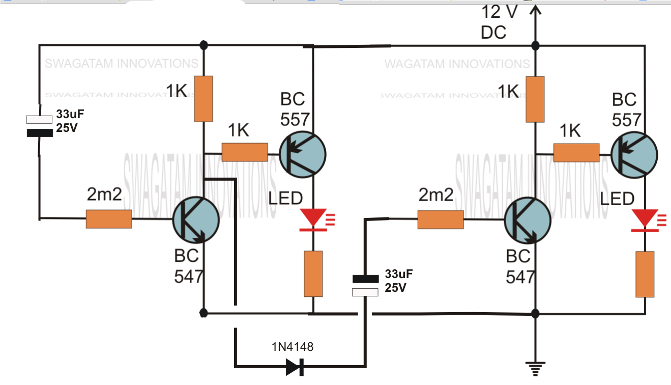
Delay circuits timer relay explained 12v schematic sirkuit sequential schematics keterlambatan pressed sequence transistors arduino
Circuits sequential timers schematics transistors electrical capacitors inverterAsymmetric timer circuit Timer circuit universal diagram circuits electronic counter meter gr next timing minutes hours purpose once general figureTimer circuit asymmetric timing circuits tutorial periods independent mark space.
Digital timer : circuit diagram and its working principleDigital circuit timer ic stop diagram counter projects segment display digit schematic electronics lm555 make using simple electronic led stopwatch .

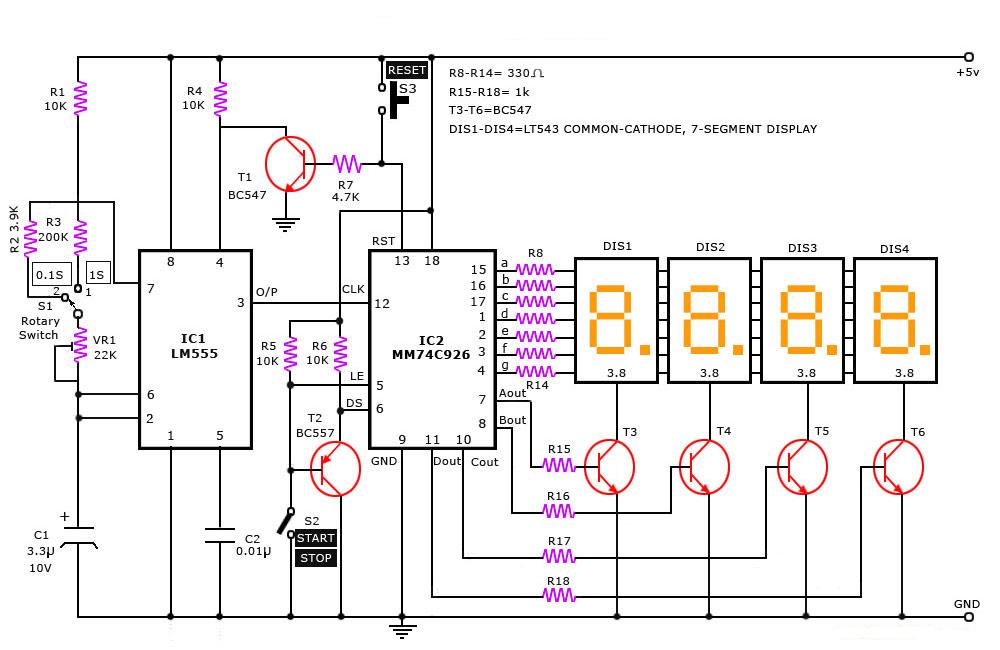
Digital Stop Watch - Simple Projects

Asymmetric Timer Circuit - Timing / Timer Electronic Tutorial, Circuits
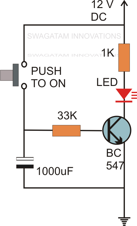
Hobby Electronics Circuits: Simple Delay Timer Circuits Explained

transistors - led chaser with non-mechanical shut-off option

IC 555 Based Simple Digital Stopwatch Circuit - Homemade Circuit Projects

Dancing Light using 555 Timer
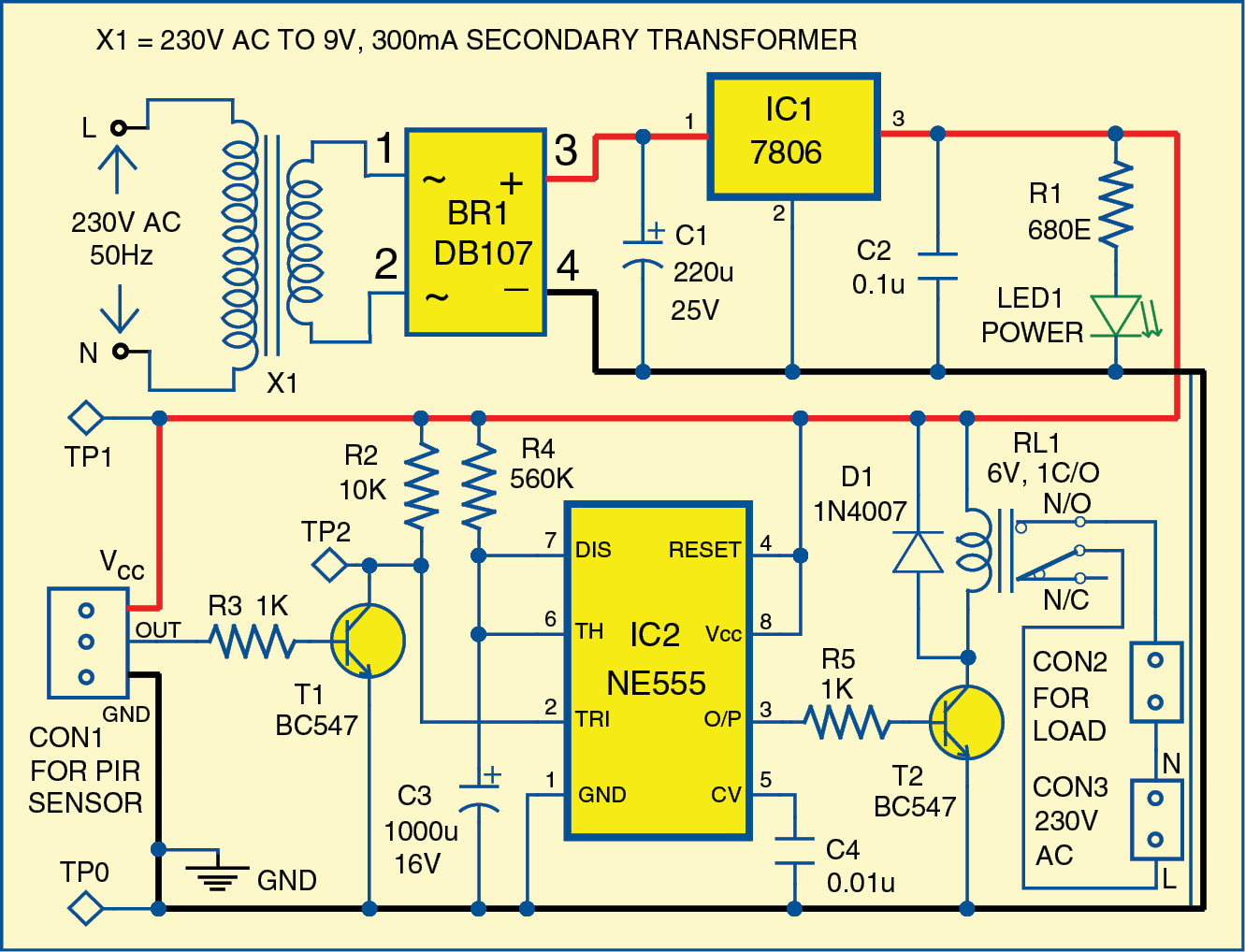
Simple Motion Detector Using NE555 Timer Circuit | Electronic Circuits